Thursday, April 26, 2012 7:27 PM Posted by Lisa Park

The Blog

In our quest to build wood pointilism, our team, Team Zoot (yes, Zoot as in the muppets) , had documented our progress in this blog. For those who are curious to know about how Franklin Olin College of Engineering group project based classes work, this documentation should give some insight.

Scoping, Ideating, Project Proposal

Posted byJordyn Burger and Lisa Park on February 24, 2012  • 

We began with getting and idea of our fields and what we are all interested in doing. As you can see above, our team is very balanced, and everyone is interested in doing very different but symbiotically beneficial parts of the project (I myself will basically be doing a bit of everything ^^).

Jordyn - Project Manager, Mechanical system, servo configuration
Casey - Mechanical
Lisa- Freelancer, coding :), mechanical, help with website, documenting
Noura - GUI, image processing, website. 

In terms of team dynamics, things are looking very good.

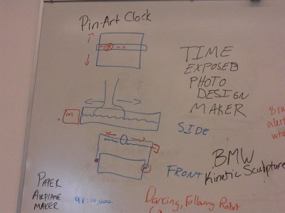
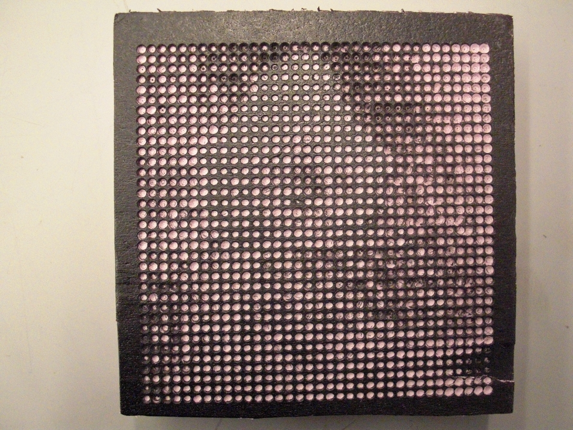
While the rest of us were getting into setting up the scope of our project for our project proposal (due march 2), Casey already started looking into ideas for how our project might look like and stumbled upon this:

http://www.engadget.com/2011/07/30/cnc-mod-carves-dot-drawing-portraits-for-your-living-room-walls/

From there we began breaking our project into pieces and getting a general idea of how to do things and when things would be due. (i'll post later how we ended up breaking our project. This part includes things like minimum deliverables, wood or foam, etc). There are approximately 9 weeks (ignoring spring break) till our final demonstration, along with two other design reviews in between, which actually doesn't really give us much time. We all agreed that it would be good to set up an accountable meeting, which would make scheduling much easier for the future (specially when two of us have UOCD...Note for all those who are intending to do group projects in the future. This is very important to do because setting up meetings every week on the go makes things even harder to try and find syncable meeting times... This will make it so that you are scheduling around the team meeting instead of scheduling your team meetings around all your other meetings). Jordyn sent an ical for Thursdays from 7-8pm.

For Team contacting and work syncing, we set up a google doc (which also had our project proposal on it) and input our contact info. Noura also set up a "text everyone" number for easy group contact.

https://docs.google.com/document/d/1wOPgAupNXiIk6mKCY9MZrfFBy4lRZtsw8i3mLezHwSQ/edit?pli=1

Noteable sites:

http://www.ehow.com/video_8000414_using-end-mills-wood-lathes.html

For Poe Day 2:

Each of us need to do some brainstorming and research for parts, budget, implementation methods, and other necessary components by Tuesday. Hopefully we would then finish our project proposal in class that day. (whoo hoooo, get ahead schedule! Our general plan is the have a more minimum deliverable done early then with thee extra time, refine it and add to our ... machine). I think i'll be looking up GUI things, how to make website, and some basic implementation methods (a little into the mech E side).

Brainstorming and outlining make all the Difference


Posted by Jordyn Burger and Lisa Park on February 28, 2012  •

I’d call this the day of decision-making.  When we first started talking today, we realized that there are a ton of hurdles to consider in this process.  Thinking about these issues allowed us to make more decisions...like whether or not we should build our own drill!  That debate took some thought.  I think, at this point, we’re at the point where we’re intimidated by the prospect of building our own drill, and are going to try and use another setup, like a dremel.  The above image is the 1st idea for our mechanical design.

Casey, being the beast he is, had already ideated the basic structure of the mechanical system [PICTURED HERE]; however, the little things he anticipated, such as high torque, are super important.  We debated whether   Turns out, breaking things into simpler steps makes the challenges seem much more manageable.  These steps looked something like this..

Things we need to do:
1) Turn a drill bit (taking torque into account)
2) Hack moter to AC power
3) Lead screw linear motion
4) CAD frame
5) Build frame
6) GUI - image processing

Minimum Deliverable: turn a drill bit -> drill a hole -> drill hole where we tell it to -> drill line of holes -> drill line of holes of varying sizes.

Maximum Deliverable: image processing, HOLE PICTURE

Turns out, scavenging parts is the best thing ever [but actually].  We found 3 stepper motors to use in our three-axis craziness, which is the best!  Their power led us to start thinking about the safety aspects of our project, since the drill itself will lead to little particles moving at quick speeds, presenting a slight hazard to the user of the wooden pointillism machine.  Hopefully, we can come up with a way to account for this risk.

Finalizing the Proposal

Posted by Jordyn Burger and Lisa Park on March 2, 2012  • 

https://docs.google.com/document/d/1wOPgAupNXiIk6mKCY9MZrfFBy4lRZtsw8i3mLezHwSQ/edit?pli=1
Done with Proposal ^^.
A bunch of basic aspects of the project are finalized and we’re done with the proposal ^^. This included a description of the image processing, and the making of the CNC drill, as well as team member responsibilities, a tentative schedule, project budget, and End of Life plan for disposal.

Research, CAD renders, and some pretty Ballin' code


Posted by Jordyn Burger and Lisa Park on March 6, 2012  • 

This is an image of our CAD of our first mechanical design.

Quick update...
1. Researching how to hack and drive our stepper motors.  So far, so good.  Now we’re understanding how H bridges are important to driving these cool kids...we just need to make some circuits!  That’s going to happen soon.

2.  Casey is a boss!  Here’s an image of the CAD that he’s been working on.
So awesome.

3.  Noura’s code is baller!  At this point, it does the following.

# getting using input
give it the file name input for the image
tell it the name you want to image preview output to be saved as
tell it how many holes horizontally the dremel will make
tell it how many holes vertically the dremel will make

# program does stuff
it opens the image
it resizes it to fit the dremel’s desired hole range
it converts it from an image to an array of numbers
it converts these RGB numbers to grayscale numbers
it converts the grayscale numbers to some uncalibrated range of hole sizes

# displaying output
it shows you the array of grayscale values
it saves the resized grayscale image to the filename you gave it so you can open that
image file and see it

Progress is abundant.  Can’t wait to see all of these aspects connect.

Program and Research mostly working

Posted by Jordyn Burger and Lisa Park on March 8, 2012  • 

Now the program calculates various hole sizes* based on the image, and then it draws those circles on the canvas to give a preview of what the sheet of wood will look like, but there's still a bug somewhere so it doesn't draw the holes in exactly the right place

*still arbitrary circle sizes in pixels but can be scaled to correspond better with real life

On the Electrical side, Noam directed us to a stepper motor controller that can withstand 3.5 amps which will give us the torque that we need so badly. (Not something H bridges can really give you) We attempted to hack the motors with some confusion.

http://parts.digikey.com/1/parts/1299258-ic-stepper-motor-drvr-2ph-25hzip-tb6560ahq-o.html

Order Stepper Motor

Posted by Jordyn Burger and Lisa Park on March 9, 2012  • 

Chris sent out an email saying he's ordering from adafruit and sparkfun for discounts if anyone needs it. We tried checking the websites out to see if we needed anything (especially the H bridges). We're probably gonna stick to the controller Noam and Tim suggested.
http://img695.imageshack.us/img695/5841/tb6560ahqa.png
http://parts.digikey.com/1/parts/1299258-ic-stepper-motor-drvr-2ph-25hzip-tb6560ahq-o.html

We also checked out adapters, but Lauren (the N.I.N.J.A) suggested checking out the dump first.

Thrifty with circuits

Posted by Jordyn Burger and Lisa Park on March 13, 2012  • 

Outside guests give great advice.  Casey had been considering working in another iteration of the mechanical system, and after chatting with today’s guest, he’s decided to go for it!  It should be done in time for our design review :).  We’re also working towards a less expensive structure, and being super thrifty in our parts scavenging.  Fun times!

We also ordered some parts from Digikey today so we can assemble our circuit.  That’s probably the area that is most grey, and the area we’ve researched so much over the last few weeks.  We decided against H-bridges, and went for stepper motor drivers  We ordered three Toshiba TB6560AHQ motor drivers, which should be here soon!

Wow! There's an awesome site called freecsstemplates.org and a youtube tutorial that explains how to edit html using dreamweaver. That saved a ton of time on the website end.

First Design Review

Posted by Jordyn Burger and Lisa Park on March 15, 2012  • 

Here's a second mechanical design based on feedback.

Tomorrow’s our first design review!  It’s both exciting and nerve wracking to know that our class is going to see what we’ve been up to.  Looking back, a lot of what we’ve been doing is decision making and research.  We’ve got some preliminary mechanical design, we’ve got some code (Noura had just gotten the code to properly pointillize images), and we’ve got some information about circuits.  Next comes feedback on the two different mechanical systems Casey’s come up with, we’ll go from there!

Feedback makes a big Difference

Posted by Jordyn Burger and Lisa Park on March 16, 2012  • 

The verdict: Casey’s second CAD design is the plan for the mechanical structure of the system!  A few tweaks, and we’ll have something to go with! Otherwise, we're waiting for the electronic parts to arrive.

Spring Break Happens.

Annnnnd we're back

Posted by Jordyn Burger and Lisa Park on March 27, 2012  • 

Noura started getting more creative with the possibilities of integrating the web with the pointillism code, allowing web surfers to upload a picture and get a pointillized version of their image. Chris advised that this may not be possible because it jeopardizes the security of the server. It was a cool thought though.

Casey worked on the budget of the mechanical components (trying to lower the costs). We managed to find some lead screws lying around and whatnot. Also apparently if a girl comes in to buy metal from Admiral's (store), metal is free.

For the circuit, we’ve got chips, we’ve got parts, and we’ve got lots to do!  Today, we started to build a circuit, using the diagram from the data sheet and advice from our awesome NINJA [Tim].  Lisa and Jordyn spent the time soldering the Toshiba chips and figuring out how to wire up the circuits. Later that day, we managed to wire up one of them using the data sheets (with some confusion regarding the function of certain pins on the chips).

We got a drill!

Posted by Jordyn Burger and Lisa Park on March 29, 2012  • 

It’s nice to walk to our weekly out of class meeting and get excited about something every week.  This time, it was Casey’s new purchase from Harber Freight. We got a mini router!
[insrt pictureof router]. comment under picture: "I love you casey! I love guys who are thrifty!" Noura

We spent the first bit of our meeting playing with different bits, looking at widths and depths of holes.  Priorities, man! There was a bit of a discussion regarding what different sized holes were possible. Theoretically you can have ....a lot of diff sized holes if you are using stepper motors, which wont be a problem at all. When testing out the poinllism code by restricing the number of different sized holes, 5
different sizes still brought out a distinguishable image.

Next will be tracking down a power supply.  After talking with a few classmates/Chris, we’ve decided we’re going to use PC power supply, and stop our weird attempts of trying to understand how to hack and plug things into the wall [we’re crazy, I know].  

The actual budget sheet was created.

Circuit Hooked

Posted by Jordyn Burger and Lisa Park on March 30, 2012  • 

Lisa and Jordyn finished hooking up the circuit....which didn't work at all. We found we needed an alternative 5V power source so currently we are looking around for that. (Perhaps a cell phone charger?)

PC Power Supplies are really useful

Posted by Jordyn Burger and Lisa Park on April 3, 2012  • 

Thanks to Chris's suggestion, we've discovered the use of the PC Power Supply! Hackable for an individual's need, we can draw 12V or 5V, whichever we need. A Helpme was sent out and if there is no response, we're gonna head to the local dump and see if we can grab one.

Mechanical parts arrive! Casey and Jordyn plan on being in the machine shop quite a bit.

Noura began working on the programming for the motor.

Turn it on

Posted by Jordyn Burger and Lisa Park on March 5, 2012  • 

Ack! Jordyn and Lisa discovered that when we were testing the circuit, we had forgotten to turn it on! On the other hand when we finally properly tested it today, we short circuited something. After some rewiring, we're gonna have to test it again tomorrow.

Noura and Lisa quickly proofread some code then Noura went with Casey to cut up some wood in the machine shop (we might

Things Work

Posted by Jordyn Burger and Lisa Park on April 6, 2012  • 

What happens when you put a recent ECE and a BioMechE in the land of circuits? All of the following:

1) They test the circuit for an hour, and cannot understand why it isn’t working...until two days later, they discovered they never turned the power on. Oops!
2) After learning that the power was never turned on, we turned it on...and things started smoking.  Turns out, they managed to create two short circuits between power and ground.
3) They removed the short circuits...and then discovered that they hacked the motors incorrectly! The black wire was supposed to be soldered to the green striped wire and the red to the striped blue.
4)The power resistors weren't working very well. We got in contact with Noam and Mark in order to order some new resistors and capacitors.

After all these crazy obstacles, the chips weren't burnt, the circuit finally worked, and our stepper motor turned with the help of a signal generator. Yay!

Shopity Shop, Shopity shop

Posted by Jordyn Burger and Lisa Park on April 8, 2012  • 

This weekend was full of shop fun.  We took turns shop buiddin’, hanging by the mille, machining parts.  We drilled holes in our wood, and Casey made a plan for the bushings!  Looks like our mechanical system is coming together :)

So many choices

Posted by Jordyn Burger and Lisa Park on April 10, 2012  • 

After some off-tram mille fun, Casey headed to Admiral Metal get some parts.  As much as a boss as we’ve made him out to be, he made an oopsie, and forgot his wallet.  Great thing is, our team’s pretty good at rolling with the punches, so it’ll all be ok :)

We did some quick off-hand calculations, using information from our stepper motors and lead screws to determine how many hole sizes we can have in our system.  One step of our motor turns 1.8 degrees.  Using this number, and the fact that 7200 degrees moves our lead screw one inch, we can have somewhere on the order of 700-1000!  However, because the human eye is not that precise, we’re thinking of using 10 different hole sizes.

Allen left us with an interesting thing to think about: variation due to mechanical error.  Try as we might, the system will probably not be perfectly level.  Because of this, we may have a gradient shading across the final piece made by our system.  We’re trying to find a way to compensate for this error, and it’s definitely going to be interesting.


Jordyn managed to fritz our ciruit for the upcoming design review. Lookin awesome.

Annnnd another version of the mechanical design. (wow Casey)

The arduino is workin with the motor! Mostly. There are some jerky movements that we have to debug. This will hopefully be fixed when the new parts arrive.

Casey's a straight up boss

Posted by Jordyn Burger and Lisa Park on April 13, 2012  • 

We purchased pre-oiled rods [check the specs on this] to make the bushings for our system. Casey anticipated ~8 hours in the shop...but did it in less time, and made beautiful bushings! Happy Casey is Happy.
[insert picture of casey and the bushings]

Noura was running into some issues regarding sending data over serial from Python to the Arduino...

have [0, 255] different hole sizes
so we can just use 1 byte to represent each hole size
8 in x 12 in board with .225 in holes = 35 x 53 holes = 1855 holes = 1.855 KB of memory
the arduino uno has 32 KB of memory so we should be fine
we can just connect the arduino to the laptop, load up all the hole sizes, then unplug the arduino from the laptop and we’re ready to go.  we can run the program over and over for demo day to print multiple copies of the olin logo or something.

on the arduino, have an array of bytes for the hole sizes
on python, use struct.pack to make it store ints as one byte each

typedef struct {
   unsigned short a;
   unsigned char b;
} message;
message msg;
byte * msgbytes = & msg;
msgbytes[0] = whatever   
msgbytes[1] = whatever
msgbytes[2] = whatever

Lisa finished wiring up the rest of the circuits (whoohooo parts have arrived!) When tested, the motors work beautifully. Spent the rest of the time breading wires, after all, a neat circuit is a happy circuit.

Coming Together

Posted by Jordyn Burger and Lisa Park on April 17, 2012  • 

Our three subcircuits are officially one!  Our power resistors and capacitors made it in the mail last week, so we were able to put them together.  They’ve been tested, and we have working circuits! Yay! Now we just need to interface things on that front. =]

As you know, math is fun [shock].  Today included more calculations relating the amount of rotations of the stepper to the depth of the hole drilled.

Casey’s doing some final CAD, and Noura’s considering switching from windows to linux.  She really wanted to have it in windows with the idea that it is more accessible to the outside world.  Lisa’s working on the circuit.  We have all three, and they should be done probably in the first half of class! Yay! - Gonna be working on website now for the rest of the duration ^^


Python will send a grayscale value to the arduino
the arduino will convert it into the number of steps to make the z motor make
here are our calculations for this conversion

/* we receive a grayscale value x in [0, 255] from Python's image
     processing
  want to conver this into the number of steps to tell the motor
     to make in the vertical (z) directions
  
  255 / x is the fraction of the square grid we want to be white
  
  pi * holeRadius^2 / gridWidth^2 is the fraction of the grid
     that will be white when we make a hole of this size
  
  holeRadius = squareroot( (gridWidth^2 * 255)/(pi * x) )
  
  simplify this to
  holeRadius = gridWidth * sqrt(255/pi) / sqrt(x)
  
  depthToGoDown in inches = holeRadius * dremelHeight/dremelWidth
  
  zsteps to go down this amount
      = depthToGoDown * degreesPerIn/degreesPerStep
      
  we also have to go down enough zsteps to reach the very top of
      the board
  
  zsteps = holeRadius * dremelHeight/dremelWidth
            * degreesPerIn/degreesPerStep
            + zstepsToBoard
  
  simplify this to
  zsteps = gridWidth * sqrt(255/pi) * dremelHeight/dremelWidth
           * degreesPerIn/degreesPerStep * 1/sqrt(x)
           + zstepsToBoard
            
  dremelHeight = 0.20 in, based on our dremel bit
  dremelWidth = 0.25 in, based on our dremel bit
  degreesPerIn = 7200 degrees, based on our lead screws
  degreesPerStep = 1.8 degrees, based on our stepper motor
  zstepsToBoard = ? steps, based on our setup
  gridWidth = ? in, we might change this to calibrate,
                    so leave it as a variable for now
  
  simplifies to
  zsteps = 28830.0325 * gridWidth * 1/sqrt(x) + zstepsToBoard
  where x is our grayscale value in [0, 255]

The goals for this week include having all of the parts done, and starting assembly.  If we can put things together, we can move forward with interfacing.  It’s a bit daunting, especially with 3 weeks to go, but we can do it!

Mechanical Mishap

Posted by Jordyn Burger and Lisa Park on April 19, 2012  • 


Uh oh, Our mechanical components do not fit! The dimensional tolerances that we want we just can’t get them...Need, to talk to Chris!
Also we found out today that Noura won’t be able to pull off any all nighters if we need to pull one due to dog sitting. I don’t think we’ll have a problem regarding this though.

plan it out

Posted by Jordyn Burger and Lisa Park on April 20, 2012  • 

After the *fun* and *exciting* week for the mechanical system, we’re replanning the next few weeks, and setting more deadlines!  Sounds like this weekend will be full of machining.  After quickly redesigning the base of the system, we’re remaking the parts out of box aluminum we found in the back of the classroom.  After that, we have to remake 4 bushings, make two plates for the drill-holding device, remake the vertical supports, and drill/tap holes into all of these parts.  It’s a pretty hefty list, but we’re all ready for a weekend of cutting fluid!

A lot of today was chatting with professors [see images of us getting advice].  Then, we essentially split once more, as Casey went to the shop, and the rest of us stayed upstairs.  Sad that only one of us is trained on the mille/lathe!

Arduino and motors

Posted by Jordyn Burger and Lisa Park on April 24, 2012  • 

Past weekend, Noura, Jordyn and Lisa were trying to get the motors spinning from the arduino, with some trouble....With many hours, here are the lessons learned:

1. Remember not to directly connect power to ground. Things get really hot.
2. If you are extracting power from the pc power supply, don’t additionally extract power from the arduino...it messes things up.
3. Look at the stepper motor data sheet before trying any software hardware integration. It pretty much tells you everything you need.
4. It helps to know the hardware when working on the software.
5. Apparently the computer model matters for determining whether or not the arduino is powered correctly.
6. It matters where you decide to input the power and ground. The motors work much better when you plug them in between the two stepper motor drivers instead of at the end. This most likely has something to do with the stepper motors sucking power away from each other

Turns out our motor running code works on one person’s computer and not the others! And for it to work smoothly, the computer needs to be plugged in with its charger. Adventure.

Steady progress

Posted by Jordyn Burger and Lisa Park on April 26, 2012  • 

It has been confirmed that data is being properly sent over to the arduino with the motors smoothly responding. (Whoohoo Noura!). Casey got some more assembly done and now our mechnical component looks beautiful. Progress on the website!

Beautiful Mechanical System

Posted by Jordyn Burger and Lisa Park on April 27, 2012  • 

ITS SO PRETTY I COULD DIE.
Look, a mechanical system! Pretty, isn’t it?  Casey was not in the classroom today because he was finishing the last few mille parts left!  The circuits are cooperating [lisa, if you have a video?].  We drilled holes into our base board [MDF], so we can secure it to the system!  We noticed that the z-axis motor does not “go back in time.”  We definitely need to fix that, since that would mean our drill stays in the foam the entire time the code is running.
So the hope is that the the motors can begin to be interfaced with the mechanical system, and we can make things move! [yay]

So far we have tested Noura’s code version 1 2 and 3 which all work fine (slowly adding more features such as allowing user to choose the size, choose the image file, and giving the user a preview)

Chip Blown

Posted by Jordyn Burger and Lisa Park on May 1, 2012  • 

We ended up blowing a driver last night when testing Noura’s code version 4. O_o we had to order a couple new drivers. In the meantime we’ll have to borrow someone else’s driver (hopefully maybe tim or noam) Gah what’s with these drivers! Then again the one that blew was the one we thought we might have blown when we were testing the motors for the very first time.

On the mechanical side, Casey has virtually finished building the structure and is now ready to test with the electrical component. He had bought two new routers one which is much larger than the other (and hopefully capable of drilling wood?) to replace the one that we broke. Unfortunately, the large one may be too heavy causing the lead screws and slides to stick, though it does drill rather beautifully into the foam.

All Your Base belong to us

Posted by Jordyn Burger and Lisa Park on May 2, 2012  • 

Sweet! The motors are turning the lead screws perfectly when we finally synced the mechanical system and the electrical system. (Stepper Motors are properly screwed in) After Casey and Jordyn attached the base that will hold the foam board (which required some major fine tuning with holes) we called it a day. All that is left is for Noura to fine tune the code to make sure that the mechanical system is moving as we intend it to. Oh yeah, and we have the website to finish.

Drivers Blown

Posted by Jordyn Burger and Lisa Park on May 4, 2012  • 

Hehe, we tested out motors and they are drilling holes of different gradients ^^. Things are working properly..........or so we thought. (knock on wood)

Lovely, we somehow ended up blowing a driver. Just in case, we ordered three more drivers...which turned out to be very good because when testing our circuit several times, one of the motors of the two left were not functioning as it should be. We narrowed it down to a driver not working properly. The new drivers should arrive by Saturday and at the latest on Monday.

Done!

Posted by Jordyn Burger and Lisa Park on May 7, 2012  • 

zootzoot1

With the new drivers, everything works very smoothly ^^. We just gotta be careful of keeping the base level and we're all good! Oh, one problem through, the dremel has a tendency to push in the black paint so it is advised to use sharpie.