The Project: Software

Here is the Software component of Wood Pointillism which simply includes commented code.

Here is the Software component of Wood Pointillism which simply includes commented code.
Python
From a text-based command line interface, the user inputs the file name of the image they want to pointillize. We use the PIL image library.
Resize the image to the right size, preserving aspect ratio, using PIL.
Using PIL, convert the image to an array of integers in [0, 255]. An RGB image will be a 2D matrix of (red, green, blue) triplets. A grayscale image will be a 2D matrix of integers where 0 represents black and 255 represents white.
If image is RGB, convert to grayscale by taking a weighted average of the color values.

Tell arduino the width and height of the image:
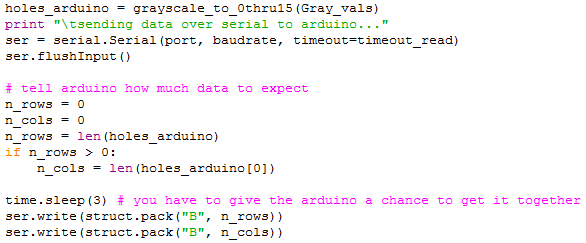
It is necessary to compress the image data before sending it to the arduino in order to avoid overflowing the arduino’s RAM. To do this, we represent each grayscale value as a value in [0, 15] and store two values in one byte.
Map the grayscale values in [0, 255] to values in [0, 15].
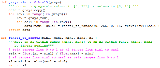
Two values are stored in each byte sent to the arduino.
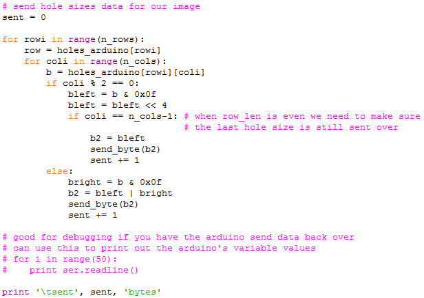
It is necessary for Python to send the information over the serial connection to the arduino slowly enough. The serial connection can be thought of as a queue. Python pushes data onto the end and the arduino pops data off the front. If Python pushes on too much data too quickly for the arduino to pop it off, the queue does not have enough memory to hold it all, so data is lost. To avoid this, Python waits a short period of time before sending each piece of data.

Drill a hole in each square on the grid
Arduino iterates over the (x, y) locations on the grid for the image and drills a hole at each square on the grid.
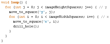
The current location of the drill is kept updated as a global variable so that the drill_hole function knows what hole size to make based on telling the z-axis motor to move up and down a certain number of steps.

For each hole, the zsteps function reads and unpacks the [0, 15] value and converts it to the number of steps the vertical motor needs to move to drill a hole of that size.

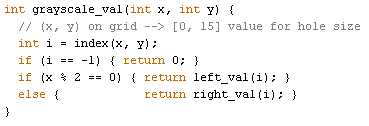
The arduino is actually storing the image data as a consecutive array of bytes, where each byte represents two pieces of data. The grayscale_val function provides an interface for accessing this data as if it were a 2D array of pieces of data in the range [0, 15].
The grayscale2zsteps function converts the grayscale value in [0, 15] to the number of steps the z-axis motor must make to form an appropriately sized hole in the board.

For more detailed information on the calculations for this conversion, for how we told the stepper motors to move, reading or accessing the data, or anything else, we invited you to view our well commented full source code files.
[let’s embed the files in the web page so they can be downloaded? Is that possible? Also, let’s provide them as .txt files which i have put in this folder too. Also worst case we can just copy the text from the .txt files to the end of this webpage or include them in links to separate pages.]
That’s it!
# Image Pointilism
# Olin College
# Principles of Engineering Project
# Team Zoot
# Jordyn Burger, Casey Karst, Lisa Park, Noura Howell
# Spring 2012
#
# Give it a digital image, and it does some image processing and sends data
# to an arduino connected by USB. The arduino has the motor control code,
# which drills holes using a dremel to make a pointilism image in a board.
#
from PIL import Image, ImageDraw
import numpy
import Tkinter as Tk
import serial
import struct
import time
timeout_read = .5 # seconds
port = 'COM3' # the serial port the arduino is on
# for debugging purposes you can use COM1 or another port
# and print what you are sending over
baudrate = 9600
#W = 35 # maximum width the physical board can take
#H = 53 # maximum height the physical board can take
# W and H are requested as input from the user, see below
# for the 'hole sizes' to send to the arduino for the actual physical image
# we will send values in the range [0, 15] to the arduino
# the arduino motor control code rescales this appropriately for the hardware
def open_image(filename):
""" returns a PIL Image object from the filename """
image = Image.open(filename)
return image
def resize_image_within(image, size):
""" image: PIL Image object
size: (width, height) tuple
returns: the image object resized to fit within size,
preserving aspect ratio """
xi = image.size[0]
yi = image.size[1]
W = size[0]
H = size[1]
k = float(yi)/float(xi)
xf = W
yf = int(k*xf)
if yf > H:
yf = H
xf = int(yf/k)
resized_image = image.resize((int(xf),int(yf)))
return resized_image
def image_to_array(image):
""" converts PIL Image object to numpy array of ints """
array_uint8 = numpy.asarray(image)
array_int = array_uint8.astype(numpy.int)
return array_int
def array_to_image(array):
""" converts numpy array of ints to PIL Image object """
c = array.astype(numpy.uint8)
image = Image.fromarray(c)
return image
def save_image(image, filename):
""" saves the image in the current directory with the given filename """
image.save(filename)
def is_RGB(vals):
return len(vals) > 0 and len(vals[0]) > 0
def RGB_to_grayscale(rgb_image_array):
""" converts an array for an RGB image into an array for grayscale
grayscale values range from 0 to 255 """
r = rgb_image_array[:, :, 0]
g = rgb_image_array[:, :, 1]
b = rgb_image_array[:, :, 2]
gray = (r*2220 + g*7067 + b*713) / 10000
return gray
def grayscale_to_0thru15(grays):
""" converts grayscale values in [0, 255] to values in [0, 15] """
data = grays.copy()
for rowi in range(len(grays)):
row = grays[rowi]
for coli in range(len(row)):
data[rowi][coli] = range1_to_range2(0, 255, 0, 15, grays[rowi][coli])
return data
def grayscale_to_hole_sizes(grays, max_hole_D):
""" input: array of grayscale [0, 255] values for an image
maximum diameter
output: array of hole sizes to use """
holes = grays.copy()
for rowi in range(len(grays)):
row = grays[rowi]
for coli in range(len(row)):
g = grays[rowi][coli]
r = int(max_hole_D/2. * (g/255.)**.5)
holes[rowi][coli] = r
return holes
def range1_to_range2(min1, max1, min2, max2, x1):
"""maps an x1 within range [min1, max1] to an x2 within range [min2, max2]
by linear scaling"""
# relx ranges from 0 to 1 as x1 ranges from min1 to max1
relx = float(x1 - min1) / float(max1 - min1)
# x2 ranges from min2 to max2 as relx ranges from 0 to 1
x2 = min2 + relx*(max2 - min2)
return x2
def ask_yes_or_no_question(question):
answer = raw_input(question)
got_input = False
while not got_input:
if answer == 'y' \
or answer == 'Y' \
or answer == 'yes' \
or answer == 'Yes':
answer = True
got_input = True
else:
if answer == 'n' \
or answer == 'N' \
or answer == 'no' \
or answer == 'No':
answer = False
got_input = True
else:
answer = raw_input("Didn't understand your " + \
"response. Please answer yes or no.\n")
return answer
def send_byte(b):
data = struct.pack("B", b)
ser.write(data)
time.sleep(.15)
# GET USER INPUT ####################################
print "Welcome to the Pointilism Program"
input_filename = raw_input("What file do you want to pointilize?\n")
make_image_preview = ask_yes_or_no_question("Would you like to make a preview"+\
" image? (y/n) \n")
if make_image_preview:
imgW = int(raw_input("\tDesired width for image preview:\n\t"))
imgH = int(raw_input("\tDesired height for image preview:\n\t"))
output_filename = raw_input("\tImage preview filename (retype same "+\
"filetype extension as input image):\n\t")
send_data_to_arduino = ask_yes_or_no_question("Would you like to send data to"+\
" the arduino? (y/n) \n")
if send_data_to_arduino:
W = int(raw_input("\tDesired width for physical image (must be an " +\
"integer greater than 0 and less than or equal to 47):\n\t"))
H = int(raw_input("\tDesired height for physical image (must be an " +\
"integer greater than 0 and less than or equal to 47):\n\t"))
picture = open_image(input_filename)
# MAKE IMAGE PREVIEW ##################################
if make_image_preview:
image = resize_image_within(picture, (imgW, imgH))
vals = image_to_array(image)
if (is_RGB(vals)):
Gray_vals = RGB_to_grayscale(vals)
else:
Gray_vals = vals
max_hole_D = 10
holes_PIL = grayscale_to_hole_sizes(Gray_vals, max_hole_D)
canvW = imgW * max_hole_D
canvH = imgH * max_hole_D
im = Image.new('L', (canvW, canvH), 0)
draw = ImageDraw.Draw(im)
# draw a circle for each hole
for rowi in range(len(holes_PIL)):
row = holes_PIL[rowi]
for coli in range(len(row)):
# size of hole
r = holes_PIL[rowi][coli]
# where to draw hole
x = coli * max_hole_D
y = rowi * max_hole_D
center = int(max_hole_D / 2)
draw.ellipse((x+center-r, y+center-r, x+center+r, y+center+r), \
fill='white')
im.save(output_filename)
# SEND DATA TO ARDUINO OVER SERIAL ##################
if send_data_to_arduino:
image = resize_image_within(picture, (W, H))
vals = image_to_array(image)
if (is_RGB(vals)):
Gray_vals = RGB_to_grayscale(vals)
else:
Gray_vals = vals
holes_arduino = grayscale_to_0thru15(Gray_vals)
print "\tsending data over serial to arduino..."
ser = serial.Serial(port, baudrate, timeout=timeout_read)
ser.flushInput()
# tell arduino how much data to expect
n_rows = 0
n_cols = 0
n_rows = len(holes_arduino)
if n_rows > 0:
n_cols = len(holes_arduino[0])
time.sleep(3) # you have to give the arduino a chance to get it together
ser.write(struct.pack("B", n_rows))
ser.write(struct.pack("B", n_cols))
# send hole sizes data for our image
sent = 0
for rowi in range(n_rows):
row = holes_arduino[rowi]
for coli in range(n_cols):
b = holes_arduino[rowi][coli]
if coli % 2 == 0:
bleft = b & 0x0f
bleft = bleft << 4
if coli == n_cols-1: # when row_len is even we need to make sure
# the last hole size is still sent over
b2 = bleft
send_byte(b2)
sent += 1
else:
bright = b & 0x0f
b2 = bleft | bright
send_byte(b2)
sent += 1
# good for debugging if you have the arduino send data back over
# can use this to print out the arduino's variable values
for i in range(100):
print ser.readline(),
print '\tsent', sent, 'bytes'
ser.close()
print 'The Pointilism Program has finished.'
/*
* 00000 0000 00 0 0 00000 00 0 00 000 0 0
* 0 0 0 0 00 00 0 0 00 0 00 0 0 00 00
* 0 0 0 0 00 0 0 0 0 00 0 00 0 0 0 0
* 00000 0 0 00 0 0 0 0 00 0 00 0 0 0
* 0 0 0 00 0 00 0 00 0 00 0 0 0 0
* 0 0000 00 0 0 0 00 0000 00 000 0 0
*
* PoE Team Zoot
* Jordyn Burger, Lisa Park, Casey Karst, Noura Howell
* Olin College of Engineering
* Spring 2012
*/
/****************************************************************
PHYSICAL PARAMETERS
*****************************************************************
* variables based on our machine
*
* Note: updating these variables does not automatically update
* all variables that depend on them. if you change any of the
* variables in this section, you should recalculate the variables
* listed in this comment block.
*
* variable_to_recalc (section whose comment block shows how to
* calculate its value)
*
* graysLen (store & read grayscale values from python)
*
* conversionFactors (drilling a hole)
*/
int motorSteps = 200; // number of steps for motor to go 360 degs
float degreesPerStep = float(360)/float(motorSteps); //degs motor turns per step
int degreesPerIn = 5760; // degrees to rotate lead screws
// 16 full rotations to move them
// forward 1.0 inches
int zstepsToBoard = 150; // vertical steps to just touch the board,
// making no hole (calculated in the
// section "drilling a hole")
float dremelHeight = 0.16; // inches, based on our dremel bit
float dremelWidth = 0.235; // inches, based on our dremel bit
int boardWidth = 10; // inches
int boardHeight = 10; // inches
float gridWidth = 0.21; // the board is divided into a grid of
// squares of this width. we drill 1 hole
// in each square
int boardWidthSquares = boardWidth / gridWidth; // 47
int boardHeightSquares = boardHeight / gridWidth; // 47
float delayTime = 1.25; // depends on our motors
//float delayTime = 2.5; // also works
int motorPinx1 = 6;
int motorPinx2 = 7;
int motorPiny1 = 12;
int motorPiny2 = 13;
int motorPinz1 = 10;
int motorPinz2 = 11;
/*
int motorPinx1 = 6;
int motorPinx2 = 7;
int motorPiny1 = 10;
int motorPiny2 = 11;
int motorPinz1 = 12;
int motorPinz2 = 13;
*/
// clockwise or counterclockwise defaults for each motor
// change from high to low or vice versa to reverse the motor's
// direction
char high = HIGH;
char low = LOW;
char motorXhilo = high;
char motorYhilo = low;
char motorZhilo = high;
/****************************************************************
MOTOR STEPPING
****************************************************************/
void one_step(int motorPin) {
digitalWrite(motorPin, HIGH);
delay(delayTime);
digitalWrite(motorPin, LOW);
delay(delayTime);
}
void move_steps(char coordinate, int nsteps) {
Serial.print("move_steps "); Serial.print(coordinate); Serial.print(nsteps);
Serial.print("\n");
int motorPin = choose_motor_pin(coordinate);
if (nsteps < 0)
reverse(coordinate);
int n = abs(nsteps);
for (int i = 0; i < n; i++)
one_step(motorPin);
if (nsteps < 0)
reverse(coordinate);
}
void reverse(char coordinate) {
Serial.print("reverse "); Serial.print(coordinate);
char dir = get_current_direction(coordinate);
Serial.print("\tcurDir "); Serial.print(dir == HIGH ? "high":"low");
Serial.print("\n");
int motorPin = choose_motor_pin_2(coordinate);
if ( dir == high ) {
digitalWrite(motorPin, low);
update_direction(coordinate, low);
}
else {
digitalWrite(motorPin, high);
update_direction(coordinate, high);
}
}
char get_current_direction(char coordinate) {
switch (coordinate) {
case 'x':
return motorXhilo;
case 'y':
return motorYhilo;
case 'z':
return motorZhilo;
}
return 'x'; // hopefully this will cause an error
}
void update_direction(char coord, char hilo) {
switch (coord) {
case 'x':
motorXhilo = hilo;
break;
case 'y':
motorYhilo = hilo;
break;
case 'z':
motorZhilo = hilo;
break;
}
}
int choose_motor_pin(char coordinate) {
// returns pin 1 of the x, y, or z motor
int motorPin = 0;
switch (coordinate) {
case 'x':
motorPin = motorPinx1;
break;
case 'y':
motorPin = motorPiny1;
break;
case 'z':
motorPin = motorPinz1;
break;
}
return motorPin;
}
int choose_motor_pin_2(char coordinate) {
// returns pin 2 of the x, y, or z motor
int motorPin = 0;
switch (coordinate) {
case 'x':
motorPin = motorPinx2;
break;
case 'y':
motorPin = motorPiny2;
break;
case 'z':
motorPin = motorPinz2;
break;
}
return motorPin;
}
/****************************************************************
STORE & READ GRAYSCALE VALUES FROM PYTHON
*****************************************************************
* we divide the board into a grid of squares
* we will drill a hole in each square
*
* boardWidth = 8.0 inches
* boardHeight = 12.0 inches
* gridWidth = 0.225 inches
* boardWidthSquares = int(boardWidth / gridWidth) squares
* boardHeightSquares = int(boardHeight / gridWidth) squares
* numSquares = boardWidthSquares * boardHeightSquares
* we receive numSquares grayscale values from python
* store them in an array with numSquares elements
* but the length of an array must be #define as a constant
* (#define statement is below this comment block)
*
* make sure arduino has enough memory for grays[]:
* for our current values,
* boardWidthSquares = 47 squares wide
* boardHeightSquares = 47 squares high
* numSquares = 47 * 47 = 2209 squares
* if we used 1 byte to store the grayscale value for each hole
* then we would need 2.209 KB
*
* arduino uno R3 has ATmega328 microcontroller
* flash memory 32 KB
* SRAM 2 KB
* EEPROM 1 KB
*
* trying to store 1.855 KB in SRAM breaks the program
* but storing half of that in SRAM is OK
* so we use half a byte for each hole size,
* meaning we can have 16 different hole sizes
*
* our board is 47 squares wide by 47 squares high.
* because the width is odd, when we store the hole sizes
* in pairs the last hole size in each row will be in a byte
* by itself on the left half of the byte
* so we need ceil(47/2) * 47 = 1128 bytes at most
*/
int imageWidthSquares = 0; // squares, will get this from Python
// will be at most boardWidthSquares
int imageHeightSquares = 0; // squares, will get this from Python
// will be at most boardHeightSquares
#define graysLen 1128 // hard coded based on above comment block
// this is the max number of bytes needed
int graysBytes = 0; // will calculate based on imageWidthSquares
// and imageHeightSquares; this is how many
// bytes are actually being used to store
// the image data
byte grays[graysLen]; // to store the grayscale vals from Python
void read_and_store_data_from_serial() {
// reads data from python over serial
// stores data in grays[]
int temp = 0;
byte b = 0;
initialize_grays_to_zeros();
while(Serial.available() < 1) {
blink_led(1000);
blink_led(100);
}
imageHeightSquares = Serial.read();
while(Serial.available() < 1) {
delay(10);
}
imageWidthSquares = Serial.read();
set_graysBytes();
int i = 0;
while (i < graysBytes) {
if (Serial.available() > 0) {
temp = Serial.read();
b = byte(temp);
grays[i] = b;
i = i + 1;
}
}
}
void initialize_grays_to_zeros() {
for (int i = 0; i < graysLen; i++) {
grays[i] = 0;
}
}
void wait_for_bytes(int n) {
while (Serial.available() < n) {
blink_led(1000);
}
}
void set_graysBytes() {
if (imageWidthSquares % 2 == 0) {
graysBytes = imageWidthSquares/2 * imageHeightSquares;
} else {
graysBytes = (imageWidthSquares/2 + 1) * imageHeightSquares;
}
}
// grays[i] is one byte that stores two values
int left_val(int i) { return int(grays[i] >> 4); }
int right_val(int i) { return int(grays[i] & B00001111); }
int index(int x, int y) {
// (x, y) on grid --> index in grays[]
if ( x < imageWidthSquares && x >= 0 &&
y < imageHeightSquares && y >= 0 ) {
// add 1 iff imageWidthSquares is odd
int temp = imageWidthSquares + (imageWidthSquares % 2);
return (y * temp + x)/2;
} else {
return -1;
}
}
int grayscale_val(int x, int y) {
// (x, y) on grid --> [0, 15] value for hole size
int i = index(x, y);
if (i == -1) { return 0; }
if (x % 2 == 0) { return left_val(i); }
else { return right_val(i); }
}
/****************************************************************
MOVEMENT ACROSS THE BOARD IN X AND Y DIRECTIONS
******************************************************************
* to move a certain number of squares on our board, we need to
* move the x and y motors a certain number of steps.
*/
double convertSquaresToSteps = double(gridWidth)
* double(degreesPerIn) * double(motorSteps)/double(360);
int squares2steps(int squares) {
return int(convertSquaresToSteps * squares);
}
double convertStepsToInches =
double(degreesPerStep) / double(degreesPerIn);
float steps2inches(int steps) {
return float(convertStepsToInches * steps);
}
int curSquare[2] = {0, 0}; // (x, y) location on grid of squares
float curPos[2] = {0, 0}; // (x, y) location in inches
int choose_coord_index(char coord) {
int i = 0;
switch (coord) {
case 'x': i = 0; break;
case 'y': i = 1; break;
}
return i;
}
void move_to_square(char coord, int pos) {
Serial.print("move_to_square "); Serial.print(coord); Serial.print(pos);
Serial.print("\n");
int i = choose_coord_index(coord);
int d = pos - curSquare[i];
move_squares(coord, d);
curSquare[i] += d;
}
void move_squares(char coord, int d) {
Serial.print("move_squares "); Serial.print(coord); Serial.print(d);
Serial.print("\n");
int steps = squares2steps(d);
move_steps(coord, steps);
int i = choose_coord_index(coord);
curPos[i] += steps2inches(steps);
}
/****************************************************************
DRILLING A HOLE
*****************************************************************
* We need to conver the grayscale values we get from Python
* to motor steps in the vertical (z) direction
*
* deriving the variable conversionFactors
* and the function grayscale2zsteps
*
* we receive a grayscale value x in [0, 15] from Python's image
* processing, where 0 is black and 15 is white
* want to convert this into the number of steps to tell the motor
* to make in the vertical (z) directions
*
* x / 15 is the fraction of the square grid we want to be white
*
* pi * holeRadius^2 / gridWidth^2 is the fraction of the grid
* that will be white when we make a hole of this size
*
* pi * holeRadius^2 / gridWidth^2 = x / 15
*
* holeRadius = gridWidth * squareroot( x / (15*pi) )
*
* depthToGoDown in inches
* = holeRadius * dremelHeight/dremelWidth
*
* zsteps to go down this amount
* = depthToGoDown * degreesPerIn/degreesPerStep
*
* we also have to go down enough zsteps to reach the very top of
* the board
*
* zsteps = holeRadius * dremelHeight/dremelWidth
* * degreesPerIn/degreesPerStep
* + zstepsToBoard
*
* simplify this to
* zsteps = gridWidth * sqrt(1/(15*pi))* dremelHeight/dremelWidth
* * degreesPerIn/degreesPerStep * sqrt(x)
* + zstepsToBoard
*
* dremelHeight = 0.16 in, based on our dremel bit
* dremelWidth = 0.235 in, based on our dremel bit
* degreesPerIn = 5760 degrees, based on our lead screws
* degreesPerStep = 1.8 degrees, based on our stepper motor
* zstepsToBoard = ? steps, based on our setup
* gridWidth = ? in, we might change this to calibrate,
* so leave it as a variable for now
* (gridWidth is declared in the section called
* "Store & Read Grayscale Values from Python")
*
* simplifies to
* zsteps = 317.381445 * gridWidth * sqrt(x) + zstepsToBoard
* where x is our grayscale value in [0, 15]
*
* calculating zstepsToBoard:
* we zero the drill by pushing it down until the tip just
* touches the board and then raising it back up by half a turn
* of the vertical lead screw. the lead screws take 16 full
* turns to move 1.0 in, so half a turn moves them 1/32 in.
* so the drill at its highest point is 1/32 inches from board
*
* 1/32 in * degreesPerStep / degreesPerIn = 100 steps
* but there's human error in turning the lead screw half a turn
* so we add in an extra 50 steps for good measure
* so zstepsToBoard = 150 steps
*/
double conversionFactors = 317.381445;
int grayscale2zsteps(int gray) {
return int(conversionFactors * gridWidth * sqrt(gray)
+ zstepsToBoard);
}
int zsteps(int x, int y) {
int gray = grayscale_val(x, y);
return grayscale2zsteps(gray);
}
void drill_hole() {
int steps = zsteps(curSquare[0], curSquare[1]);
move_steps('z', steps);
delay(500);
move_steps('z', -1 * steps);
}
/****************************************************************
BLINKING THE LED - USEFUL FOR COMMUNICATING STATUS
*****************************************************************/
#define ledPin 13
void blink_led(int duration) {
digitalWrite(ledPin, HIGH);
delay(duration);
digitalWrite(ledPin, LOW);
delay(duration);
}
/***************************************************************
PUTTING IT ALL TOGETHER - MOTOR CONTROL CODE
***************************************************************/
void setup() {
// Initialize motors
pinMode(motorPinx1, OUTPUT);
pinMode(motorPiny1, OUTPUT);
pinMode(motorPinz1, OUTPUT);
pinMode(motorPinx2, OUTPUT);
pinMode(motorPiny2, OUTPUT);
pinMode(motorPinz2, OUTPUT);
// counter clockwise or clockwise for motors
digitalWrite(motorPinx2, motorXhilo);
digitalWrite(motorPiny2, motorYhilo);
digitalWrite(motorPinz2, motorZhilo);
// Initialize the LED for debugging purposes
pinMode(ledPin, OUTPUT);
digitalWrite(ledPin, LOW);
// Initialize the Serial port:
Serial.begin(9600);
Serial.flush();
read_and_store_data_from_serial();
}
void loop() {
for (int j = 0; j < imageHeightSquares; j++) { // y
move_to_square('y', j);
for (int i = 0; i < imageWidthSquares; i++) { // x
move_to_square('x', i);
drill_hole();
Serial.print("x= "); Serial.print(curSquare[0]);
Serial.print(" y= "); Serial.print(curSquare[1]);
Serial.print(" g= "); Serial.print(grayscale_val(i,j));
Serial.print(" xDir= "); Serial.print(get_current_direction('x')==HIGH ? "high":"low");
Serial.print(" yDir= "); Serial.print(get_current_direction('y')==HIGH ? "high":"low");
Serial.print("\n");
}
}
move_to_square('x', 0);
move_to_square('y', 0);
/*
int y = curSquare[1];
Serial.print("y= "); Serial.print(y);
Serial.print("\n");
move_to_square('y', y + 1);
if (y % 3 == 0)
move_to_square('y', y - 3);
int x = curSquare[0];
Serial.print("x= "); Serial.print( x);
Serial.print("\n");
move_to_square('x', x + 1);
if (x % 4 == 0)
move_to_square('x', x - 3);
*/
/*
int y = curSquare[1];
Serial.print("y= "); Serial.print(y); Serial.print("\n");
move_to_square('y', y+1);
delay(500);
/*
int x = curSquare[0];
Serial.print("x= "); Serial.print(x); Serial.print("\n");
move_to_square('x', x+1);
delay(500);
*/
}